The Battery Management System: The Brain of liFePO4 Battery
A Battery Management System (BMS) of lifepo4 battery serves as the critical brain for both power and energy storage battery packs. These packs contain dozens or even hundreds of individual cells. Managing this complex network requires sophisticated technology. The BMS ensures personnel safety and battery protection. It also meets power demands and extends the overall battery life. This system constantly monitors voltage, temperature, and current. It optimizes performance through State of Charge (SOC) estimation and cell balancing. The BMS also provides essential fault protection against overvoltage, overcurrent, and overtemperature conditions. Without a reliable BMS, modern battery packs cannot operate safely or efficiently. Its role is fundamental to the entire energy storage ecosystem.
Core Functional Modules of the BMS
The core function of the BMS relies on accurate state estimation of individual cells. Specialized hardware collects the necessary raw data. The Analog Front End (AFE) chip precisely measures cell voltages. Hall effect sensors capture the total current flowing through the pack. NTC thermistors monitor temperatures at critical locations. Additional sensors can detect pressure, smoke, or other abnormal conditions. The system then feeds this data into advanced algorithms. It uses models like the Extended Kalman Filter for real-time estimation. These calculations determine key states including State of Charge (SOC) and State of Health (SOH). It also calculates power capability (SOP), remaining energy (SOE), and safety status (SOS). For internal management, the BMS of lifepo4 battery controls charge and discharge power limits. It restricts charge and discharge times based on these internal states. Externally, the BMS communicates this vital information. It sends data and commands to the vehicle and charger systems. This ensures perfect coordination between the battery and external devices.
Distributed System Architecture Explained
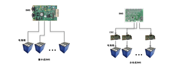
Modern BMS architectures often use a distributed model for large packs. A flat management structure becomes unreliable with hundreds of cells. Therefore, the system adds an intermediate layer of control. Smaller units, called Cell Supervision Circuits (CSCs), handle local tasks. These CSCs manage information acquisition for a specific group of cells. They then report this data to the central master control board via a bus. This approach reduces the processing load on the main controller. We can further subdivide distributed architectures into several types. A star topology connects each CSC directly to the master unit. This offers strong interference resistance but requires complex wiring. A bus topology connects multiple CSCs on a shared CAN network. This method is currently the most common in the industry. It provides balanced power consumption but relies heavily on bus health. A daisy chain links CSCs in a series, transmitting data hop-by-hop. This design simplifies wiring and suits systems with clearly layered modules.
Functional Layers and Hardware Components
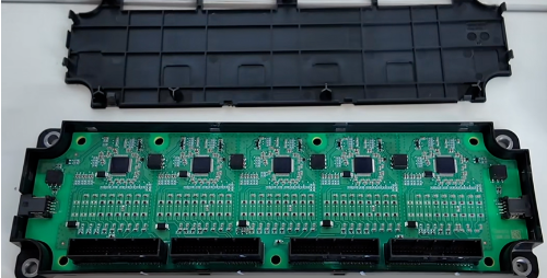
The BMS software architecture divides into three distinct functional layers. The physical layer handles all direct measurements from the battery. It collects voltage, current, and surface temperature data for upper layers. The core layer represents the system’s critical intelligence center. It uses models and algorithms to estimate internal states like SOC. The management layer acts upon this internal state information. It controls charging and discharging to ensure safe and efficient operation. The hardware architecture provides the physical foundation for these functions. A typical distributed BMS hardware includes a Master Control Unit (BMU). This unit contains a high-performance microcontroller with ASIL-D safety compliance. It features isolated power supplies and robust communication interfaces like CAN. The Slave Control Units (CSCs) contain the AFE chips and balancing circuits. They host the voltage and temperature acquisition hardware for their cell groups. The system also integrates various sensors and protection circuits. Hall sensors or shunts provide current measurement for the entire pack.
Execution, Protection, and Future Outlook
The BMS hardware includes critical execution and protection components. High-voltage DC contactors control the main power path for charging and discharging. A pre-charge circuit prevents damaging current surges during initial startup. It uses a resistor and contactor to slowly charge the bus capacitance. Fast-acting fuses provide primary protection against catastrophic short circuits. Secondary protection devices, like resettable PTC fuses, guard against local overcurrent events. The system also distributes actuators and protection elements throughout the pack. These components work together to ensure safe operation under all conditions. The BMS continues to evolve with advancements in algorithms and hardware. Future systems will feature even more accurate state estimation capabilities. They will enable faster charging, longer life, and higher safety standards. This technology remains the cornerstone of the entire electrification movement. It empowers everything from electric vehicles to grid-scale energy storage solutions.